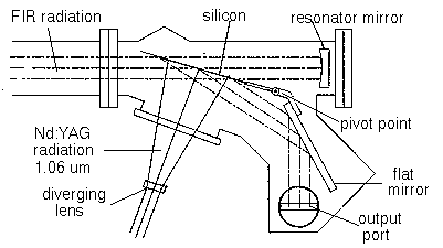
Both the UCSB FIR-FEL and MM-FEL have cavity dump couplers for generation of short, intense, radiation pulses. Stored intracavity power can be more than an order of magnitude greater than outcoupled power. If all of this power could be suddenly switched out, a pulse of intense radiation would be generated of duration equal to the optical transit time of the resonator. This has been implemented on the UCSB FELs by installing a single-crystal plate of intrinsic silicon at Brewster's angle and illuminating it with a pulse of radiation from a Nd:YAG laser.

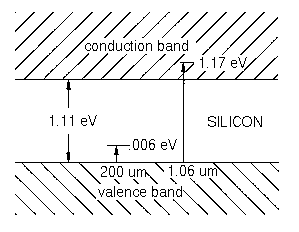
The operation of the silicon switch is shown by this energy level diagram, illustrating silicon's bandgap in relation to the
energy of FEL photons at 200 µm and Nd:YAG photons at 1.06 µm. The FEL's photons are insufficiently energetic and silicon
remains nonconducting and transparent. However, the 1.06 µm photons are sufficiently energetic to promote electrons to silicon's
conduction band. When the density of these conduction band electrons is sufficient (plasma frequency > FEL frequency) the silicon
effectively becomes a mirror. Radiation and defect recombination rates are slow (> 100 ns) in relation to the pulse length, so the
mirror remains long after the ND:YAG pulse is gone.
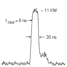
 The output pulse generated in this manner is shown for the FIR-FEL operating at 200 µm wavelength (the MM-FEL pulse is nearly
identical). Peak power is disappointingly small at 11 KW instead of the estimated 50 KW intracavity power. This is partially explained
by several factors. First, insufficient Nd:YAG power is available. External measurements show that the silicon mirror effect saturates
when Nd:YAG energy exceeds ~100 mJ/cm2. Our laser provides 1 J, but because Brewster's angle is so large in the far infrared
(74°), a large area of silicon must be illuminated (~20 cm2). The next factor is that, even with sufficient energy,
the maximum reflectivity was not observed to exceed about 50 %. Finally, insertion of the silicon adds about 5 % intracavity loss under
conditions where peak intracavity power is a sensitive function of loss.
 This is a trace of the cavity dump output measured with a Schottky detector. Pulse characteristics are 11 KW peak power, 30 ns width,
and 9 ns rise time (rise time is determined by the Nd:YAG pulse). The stepped tail results from the reflection from the quartz output
coupling window making a second transit of the resonator.
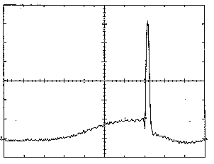
The silicon plate and first mirror pivot together to allow off Brewster angle operation. Next is an older image taken with a slower pyroelectric detector on a microsecond time scale with the plate moved away from brewster's angle to couple the whole FEL pulse. Normal FEL startup results in slowly rising intracavity power that is abruptly terminated when the Nd:Yag power is switched on. The trailing curvature is an artifact of the detector.
