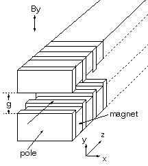
The longitudinal axis is z, and the transverse axes are x and y with the main field directed along y as shown.
The adjustment procedure for the UCSB Free-Electron Laser undulators is based on a three dimensional analytical model of the field
perturbation, along the undulator's axis, in response to a displacement of any one of the 2n ferro-magnetic pole tips,
where n is the number of pole positions (two per period).
The longitudinal axis is z, and the transverse axes are x and y with the main field directed along y as shown.
A simple two dimensional analytical model of the unperturbed fields in z and y can be derived by treating the
ferromagnetic pole tips as scaler magnetic equipotential surfaces (equivalent to assuming infinite permeability). To solve Laplace's
equation, ![]() , as a periodic boundary value problem
, as a periodic boundary value problem
![]() , a region is chosen with an upper boundary represented by the Fourier series
, a region is chosen with an upper boundary represented by the Fourier series
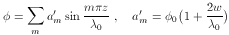
By symmetry, the lower and left potentials are zero and  on the right. The solution, by separation
of variables, yields the expansion of
on the right. The solution, by separation
of variables, yields the expansion of  as a Fourier series in z

For coordinates chosen such that at the upper boundary
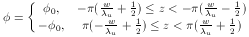
where w is the pole thickness,
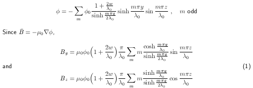
These relate the hypothetical 0 to the actual B determined numerically.
If a single pole tip is displaced by d, then the new fields, by the principle of superposition, can be modeled
as the sum of bar B from (1) and from a simple model of dipole fields created by
potential surfaces 0 and -0 of
width w at the original and displaced tip positions y and y-d. The latter results in
The simultaneous tilt of opposed pole tips generates an x axis field proportionality
These field perturbations are attenuated by the shielding effect of adjacent ferromagnetic pole tips and an empirically
derived correction of the form  was applied.
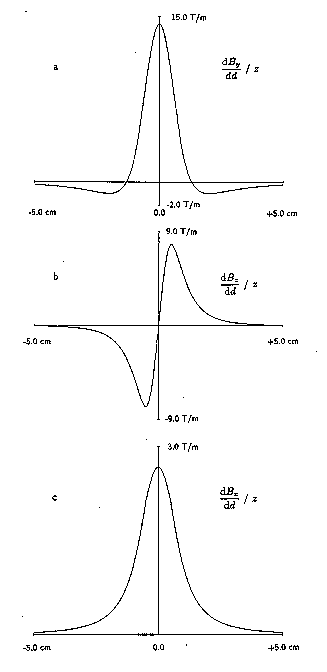 Fig. 2 a, b, and c are plots of the perturbing fields as a function of
distance from a displaced pole tip.
Fig. 2 a, b, and c are plots of the perturbing fields as a function of
distance from a displaced pole tip.
Prior to adjustment, field measurements yield a set of n values of By Bz and Bx. It should be noted that these are sampled at points along the z axis in such a way that errors are minimized. In particular, Bx and Bz measurements are prone to a large error proportional to By sin(alpha) where alpha represents an angular misalignment of the hall chips. Obviously the error is minimum where By is zero, halfway between each pole tip, so that is where x and z samples are taken. In fact, this is where the z field is maximum and must be measured anyway. The resultant pseudo values for the algorithm are then

A set of 2n equations
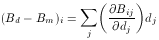
describes the difference between the desired field Bd and the measured field Bm.
The elements  , derived from he above analytical model, form a Jacobian matrix
J which, upon inversion and multiplication with
, derived from he above analytical model, form a Jacobian matrix
J which, upon inversion and multiplication with  , yields the simultaneous
solution of the 2n equations in the form of the 2n displacements d required to simultaneously correct
By and Bz
, yields the simultaneous
solution of the 2n equations in the form of the 2n displacements d required to simultaneously correct
By and Bz

Although each pole has two degrees of freedom representing in-out and tilt motions, a correlation must exist for the x correction, that is, opposing poles are constrained to tilt only by equal and opposite amounts to avoid generation of a quadrupole field. No provisions have been made for measuring such a field, but in principle, it could be done and another set of matrix elements used to correct it. For our purposes this was deemed unnecessary. To provide the required correlation, a separate J matrix is used for x. In accordance with (2), the final displacement for each screw is

The solution may be considered a quasi-Newtonian optimization, but if initial errors are not more than a few percent, convergence is rapid with about three iterations required.
